The main purpose of the exhaust manifold for Miata/MX-5, that was launched earlier onto the market, was the exhaust efficiency and the power up , but it lacked a good developing concept and sufficient empirical data. That's why its priority was just its design and image. It used to be difficult to choose out of these exhaust manifolds, that have been seen on the market that one, which would suite one's expectations.
In fact, there are different types of user demands and different engine types.
Therefore, we at Maruha would like to recommend the exhaust manifold which can be ''adjusted by the user''.
We put the experience and know-how of Maruha to the full extent even into the fine details and aim for a superb exhaust manifold that can be introduced to the market.
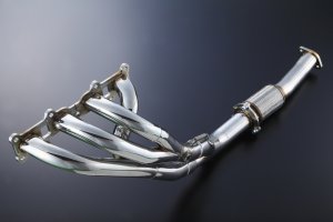
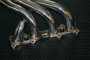
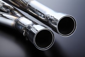
We use the flowing form type 4-2-1 for the main axis made of 42.7mm-50.8mm-60.5mm SUS 304 stainless steel.
When talking about exhaust manifold tuning, the pipe's diameter might be a very interesting point for you.
The pipe's diameter is similarly to the pipe's design significantly influencing the output characteristics.
Maruha's VP-header uses Venturi.
Taking advantage of the venturi's effect by using a 60mm/50mm variant of reducer to the main pipe (diameter 60.5mm), it is possible to change the output characteristics of the engine.
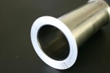
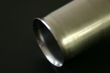
The uniquely shaped pipe is made of one plate, which is first rolled and then using a special technique turned into the venturi shape.
After the trial and error phase the integrally formed venturi got strenght and became light too.
After our verification of the effect and special characteristics of the venturi, we applied for a patent.
It's neither a utility model nor a design registration.
The reason for applying for a patent lies in our new idea of exhaust manifold tuning.
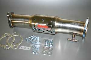
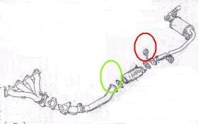
As an intermediary to the main pipe's 60.5mm part we use a flange and to it's tip we use a fixed weld flange.
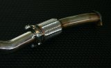
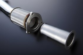
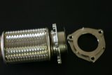
Through this construction the venturi is set up in the inside of the bellows tube (flexible tube).
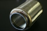
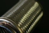
Originally, the bellows tube's purpose is to absorb the engine's, exhaust pipe's etc. vibrations and prevent the resonant and exhaust parts from cracking.
The inner part of the bellows tube secures the flexibility of the metal parts by rolling them up into a spiral shape. On the other hand, to compensate for the weak tensile strength, the outer side of these parts is covered with stainless steel mesh.
In the case of Maruha's VP-header the venturi tube is set up inside the bellows tube and prevents it from the immediate entrance of exhaust gases and acts as a thermal shield.
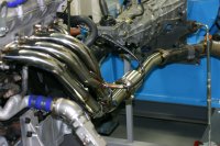
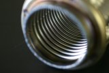
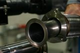
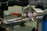
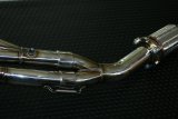
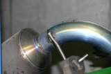
The two pictures below were taken after the tests on the engine bench.
After removing the venturi, we can see that the exhaust didn't hit the bellows tube.
To be noted:
During the production of the exhaust manifold, we use exclusive jigs and as a prerequisite we put up the flange at the same position as in the case of the genuine exhaust manifold.
However, the bellows tube shakes freely to some extent. If after the catalysis the catalytic muffler parts' installation position or the hanging change, the catalytic flange's installation position changes a little bit too.
We optimize the venturi tube's exit by turning it into a wrap shape (flaring). Because of this technique the clearance inside the bellows tube is narrow. As we already mentioned before, there are cases of interference between the inner part of the bellows tube and the venturi, following the installation changes that occur after the catalysis.
Especially in the case of engines with instable idling vibrations are strong and from the inside of the bellows tube we can sometimes hear clattering.
However in these situations we don't take any claims, that's why we ask our customers for understanding.
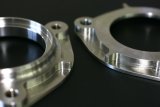
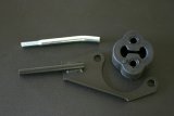
In our VP-header we use altogether 4 pieces of flange.
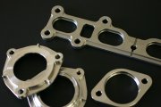
All of them are made of ALL SUS304 stainless steel or are products made by NC machining.
They are neither cheap steel nor easily made plasma or laser processings, therefore they are very accurate and beautiful final products.
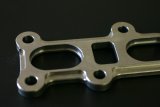
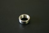
The flange processed with NC milling cutter has got a very complex shape.
Despite being 9mm thick it's strength is secured thanks to weight reduction and the outer peripheral rib.
It is our original design, it looks beautiful and doesn't get easily cracked.
One more thing about the flange's center
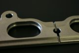
A slit that fits perfectly to the engine cylinder head is set up longitudinally in the center of the flange and in this way it becomes adherent.
The venturi is inserted into the two flanges in front of the bellows tube.
It becomes beautiful and light by NC machining.
For it is a simple construction, the exhaust cannot leak easily. Furthermore, the O-ring used together with the construction is also our original product.
In the case of maintenance it is possible to supply only the gasket.

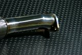
First a 60.5mm long pipe is inserted into the flange tail. It is the method of welding from the inside.
If the periphere of the pipe's joint is not welded carefully, the welding scars of the nut that fixes the catalyst set up right beside become a hindrance for suitable bolting.
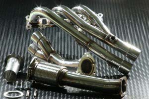
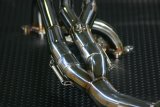
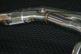
The important feature of the VP-header is not only the usage of the venturi, but also the triple slip-on construction inside of the 4-2 type pipe.
It is a well-known method in the production of racing items.
Weight reduction, absorption of oscillation and a decrease in the percentage of cracking can be noted. This technique requires very accurate processing.
We double the female pipe, that we insert into the VP-header and then insert the male pipe in between the doubled female pipe. Using this method we get a triple layer.
There is no need to mention that the preparation of these pipes requires lot of time and labor, that's why there are no these kinds of three layered constructions on the market.
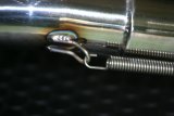
It is necessary to use a fixing spring hook with the inserted parts.
The spring hook used with the VP-header and the spring hook on the opposite side too are made of SUS304 stainless steel.
Because the hooks are circular, when they oscillate, they behave like two circles. In this way they are being protected from arbitrariness caused by vibration-induced deterioration.
Even the pipes are made of SUS 304 stainless steel.
No.1 is 42.7mm, No.2 is 50.8mm, No.3 is 60.5mm long.
No.1 takes care of the weight reduction; it's thickness is 1.2mm. The other parts' thickness is 1.5mm.
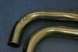
The technique of bending is very difficult that's why there are cases, when even though header has been used, usually the bent part becomes easily oval and there is some kind of transformation on it.
The looks of these pipes vary accordingly to the bending style and the craftman's abilities too.
Finally a jig is installed into the VP-header suppressing the 42.7mm pipe's transformation. The maximum diameter of the pipe is preserved and it is bent leaving a beautiful curve behind.
In the case of pipes No.2 and No.3 we kept in mind smooth fabrication while suppressing the exhaust's back pressure and the operations going on inside the engine.
All the parts are Maruha's design produced by factories that support our innovative ideas.
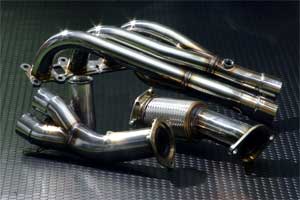
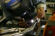
Though the last barrier is the integration. In other words the final process of the setup.
We cut the bent pipe three-dimensionally, then do the precision surface finishing of the welding surface, press the tip into an oval shape and considering the thermal strain caused by the welding we carefully set it up by a jig for exclusively this use.
Everything is put together at our factory using Maruha parts.
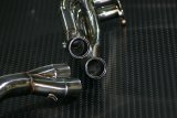
Let's see for example the letter 'Y'.
The parts assembled into 4-2-1 will surely look like the letter 'Y'. Though at Maruha we are trying to reach a high exhaust efficiency by giving priority to the angle.
Even this kind of small boss is the special result of NC processing.
The boss is as small as possible, so that it can become flexibile and light in the small engine space.
The genuine exhaust manifold is being fixed by a stay at one point - the joint of the engine and the transmission.
The stays of other companies have different shapes, but they are set up at the same place as in the case of the genuine exhaust manifold.
However if the installation's flexibility is not good or the stay is set up without enough thought, it can crack before fulfilling its function.
Our VP-header doesn't have a stay at the usual place.
We use an insertable joint together with the bellows tube and in this way the oscillation can be absorbed.
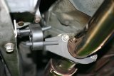
In addition we use a hanger bracket in front of the catalyst.
We thought about a hanger that can be installed simultaneously to the flange too.
The hanger is made of steel, but we made chrome plating on the car side stay and used heat-proof coating on the bracket.
We manufacture the bracket very carefully and avoid the direct welding of stays that can easily crack into the pipe.
By this technique even if the bracket cracks, the welding can be repaired and it is possible to buy from us only the bracket as a spare part.
However, in the case of the stay at the car's body it is necessary to hole drill the PFB (Plant Frame Bracket) that fixes the PPF (Power-Plant Frame) and the MT.
The hole can be easily drilled, but it is also possible to buy an already processed genuine PFB with a drilled out hole.
The exhaust efficiency is composed of the exhaust manifold, the catalyzer and the muffler.
The role of each of these parts is very important. However, after comparing the efficiency of these parts, we got to the conclusion that the most cost-effective ones are the exhaust manifold and the catalyzer.
As previosuly mentioned for NA we use a sports catalyzer. The main diameter is 60mm, that's why the compatibility with the VP-header's 60.5mm pipe is outstanding.